Active Pressure on Shear Keys in Retaining Walls
How requirements to consider active pressure on a shear key in a design can practically negate the benefits of a shear key.
Overview
In some cases, adding a shear key to a retaining wall design can unexpectedly reduce the sliding factor of safety (FoS) instead of improving it. This behavior is not a bug in the Retaining Wall module — it reflects how soil pressures are calculated on both sides of the key.How the Shear Key Affects Sliding Forces
When a shear key is added:- Active Pressure Increases
The soil on the backfill side exerts active pressure on the key.
This pressure is calculated based on the total height from the backfill surface to the bottom of the key.
Example: If you have 7 ft of backfill plus a 2 ft deep key, the active pressure is calculated over a total height of 9 ft. - Passive Pressure Increases
On the opposite side, soil provides passive resistance to sliding.
This is typically calculated from the soil in front of the footing
Note: By default, we ignore cover soil above the footing because it can be disturbed during construction, which further reduces the countering effect of passive pressure. This can be overriden with the “Consider Soil Above Toe for Stability Checks?” option in the calculator
Why Shallow Keys Can Reduce FoS
When the key depth is small:- Active pressure grows quickly because it’s based on a taller soil column behind the wall (backfill + key depth).
- Passive resistance grows more slowly because it’s based only on the depth of undisturbed soil in front of the footing.
- As a result, the increase in sliding force from active pressure can outpace the gain in resistance from passive pressure.
This means shallow keys may lower the sliding FoS until the key is deep enough for passive pressure to “catch up.”
Example
Let’s look at a basic example of a retaining wall, as shown in the image below. For simplicity and conservativeness, we assume no cover soil above the footing to passive pressure. We’ve already calculateda resisting force from friction of 2,700 lb.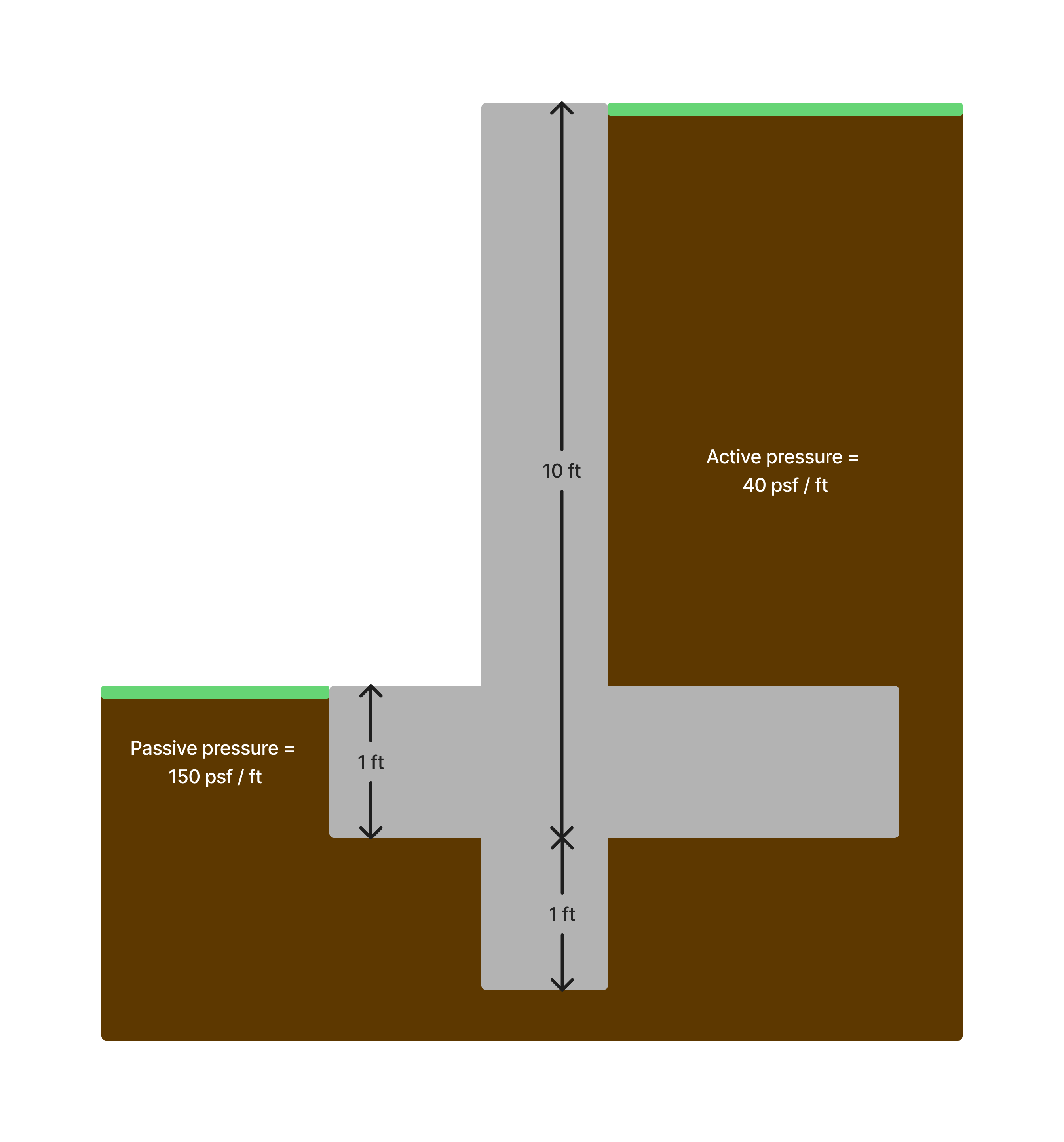
Option 1: No shear key
We calculate the factor of safety on sliding using the active pressure as the driving force, and the sum of friction and passive pressure as resisting force. **Load from active pressure: **With no shear key, we just use the 10ft of retained soil to calculate the soil pressure Load from passive pressure:
Here we consider the 1ft of soil directly against the footing for passive pressure Factor of Safety:
We can now calculate the factor of safety based on driving and resisting force: We see that the factor of safety of 1.39 is lower than the required 1.5, so the design is not good. We thus look to add a shear key to increase sliding resistance.
Option 2: Shear key, considering active pressure
Load from active pressure:In this case, since we have the shear key 1 ft deeper than the footing, we now calculate the active soil load based on a depth of 11 ft. Load from passive pressure:
Thanks to the shear key, we can now use a depth of 2 ft for the passive soil instead of the previous 1 ft, which should significantly increase resistance: A four-fold increase in passive pressure! Factor of Safety:
We now calculate the FoS based on these new loads As we can see, the factor of safety with the shear key is actually lower than without the shear key!
Option 3: Shear key, not considering active pressure
Let’s now run the same calculations but without considering active pressure on the key. **Load from active pressure: **Since we don’t consider the active pressure on the key, we just use the 10ft of retained soil to calculate the soil pressure Load from passive pressure:
Here we again use the 2 ft of soil - 1 ft from the footing and 1 ft from the key. Factor of Safety:
We can now calculate the factor of safety based on driving and resisting force: We see that if we ignore the active pressure on the key, our design does pass.
ClearCalcs Workaround: Ignore active pressure on shear key
By default, we take the conservative approach of including active soil pressure against the shear key. If you do not want this in your calculations, you can:- Go to the Shear Key Loads table.
- Set the load factors for the active soil pressure rows to 0.
Building Code Considerations
Some building codes explicitly require considering the active pressure acting on the key. In general, building codes based on the 2015 edition of the IBC and earlier contain the following phrase (see in 2015 IBC):*Where a keyway is extended below the wall base with the intent to engage passive pressure and enhance sliding stability,*lateral soil pressures on both sides of the keyway shall be considered in the sliding analysis.Starting in 2018, the IBC no longer includes that clause, but a few jurisdictions retain it in their local codes. In the IBC 2018 change notes, the following explanation is given:
The application of soil pressure on both sides of a keyway is a recent addition to the model codes, and has caused concern and opposition from the geotechnical engineering community. The keyway concept is in conflict with accepted engineering practice and the principles of soil mechanics. 2015 IBC language was vague and ambiguous with respect to lateral soil pressures on the keyway. The application of “lateral earth pressures on both sides of the keyway” is commonly interpreted to require a deepening of the active soilpressure to the bottom of the keyway. Active soil pressure requires movement of the key, which is contrary to the intent of the provision. As there has been ongoing confusion over the intent of consideration of lateral earth pressure on both sides of the keyway and confusion about the purpose of the keyway, in the 2018 IBC the requirement for a keyway is deleted. A keyway may still be used when designed using the principles of soil mechanics and accepted engineering practice.We’ve put together a non-exhaustive list of building codes requiring active pressure on shear key below:
| Building Code | Edition | Requires active pressure on shear key? |
|---|---|---|
| International Building Code | 2015 and earlier | Yes 2012: Clause 1807.2.1 2015: Clause 1807.2.1 |
| 2018 and later | Not explicitly required | |
| Florida Building Code | All recent editions | Yes 2020: Clause 1807.2.1 2023: Clause 1807.2.1 |
| New York City Building Code | All recent editions | Yes 2022: Clause 1807.2 |